PRO-RADIAL WHEEL MAKER ADDON

Pro-Radial v6.2 is a professional procedural modeling toolset for Blender, engineered specifically as the ultimate workflow for designing and making 3D wheels, rims, and tires. By combining real-time profile canvas editing, spoke array modifiers, and dynamic boolean cuts into a unified, non-destructive stack, Pro-Radial streamlines wheel creation from rough sketch to high-fidelity final mesh.
Thank you for using our tool! May God bless you on your creative journey.
Installation & Workspace Setup
Follow these quick setup steps to get the Pro-Radial system active in your Blender project environment:
-
01
Download the Addon Package
Download the latest release ZIP folder (
pro_radial.zip) from the main control download button, or use the direct link: Download ZIP File. -
02
Install inside Blender
Launch Blender. Navigate to Edit > Preferences > Add-ons. Click the Install... button in the top right, select the downloaded
pro_radial.zipfile, and click Install Add-on. -
03
Activate the Modifiers
Locate the checkbox next to Object: Pro-Radial in the Add-ons list and tick it to enable the module. Close the Preferences window.
-
04
Initialize Sidebar Control Panel
In any 3D Viewport window, press the
Nkey on your keyboard to reveal the Blender Sidebar. Select the tab labeled Pro-Radial to reveal the custom control cockpit interface.
0. Complete Design Presets
The Complete Presets panel allows you to instantly save and load entire wheel designs—including base profile layers, arrayed elements, and boolean details. This allows for rapid prototyping and iteration.
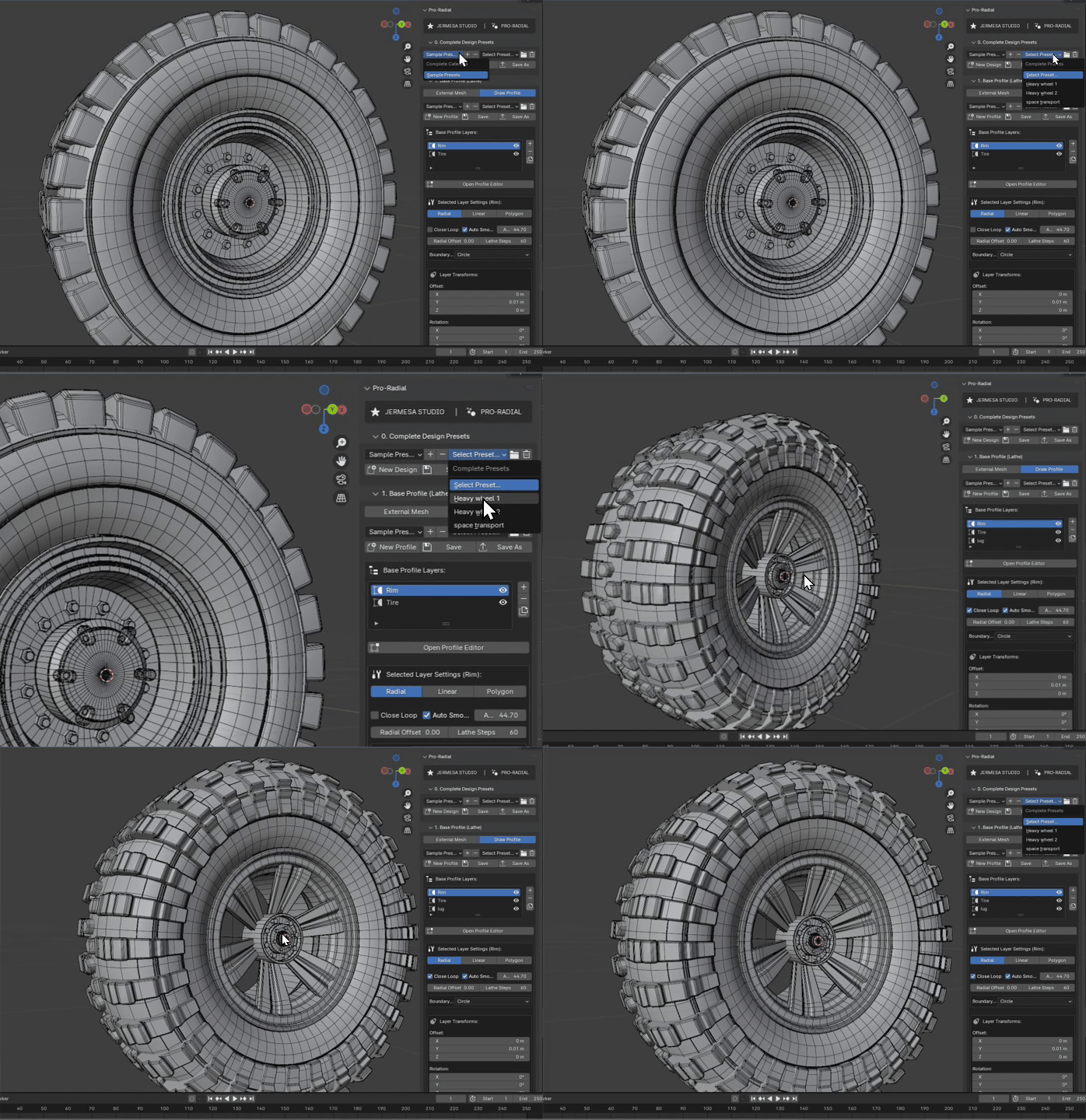
Preset Management Controls
The top panel acts as the main hub for loading base templates or custom design configurations:
Preset Categories
Organize presets into folders. Click the + button to create a new sub-folder on disk, and the - button to remove empty directories.
Presets Dropdown
Select from available preset configurations within the selected category. Selecting a preset instantly rebuilds the entire procedural stack in your Viewport.
Explore & Manage Files
Click the folder icon (Explore Presets) to open the preset directory in your OS file manager. Click the trash icon to delete presets permanently.
Save & Save As
Click Save to overwrite the active preset. Click Save As to write a new preset file. New Design wipes the canvas clean.
1. Base Profile Layers (Lathe)
The Base Profile panel defines the main rotational silhouette. It uses a lathe generator to sweep a profile curve 360 degrees around the chosen rotational axis.
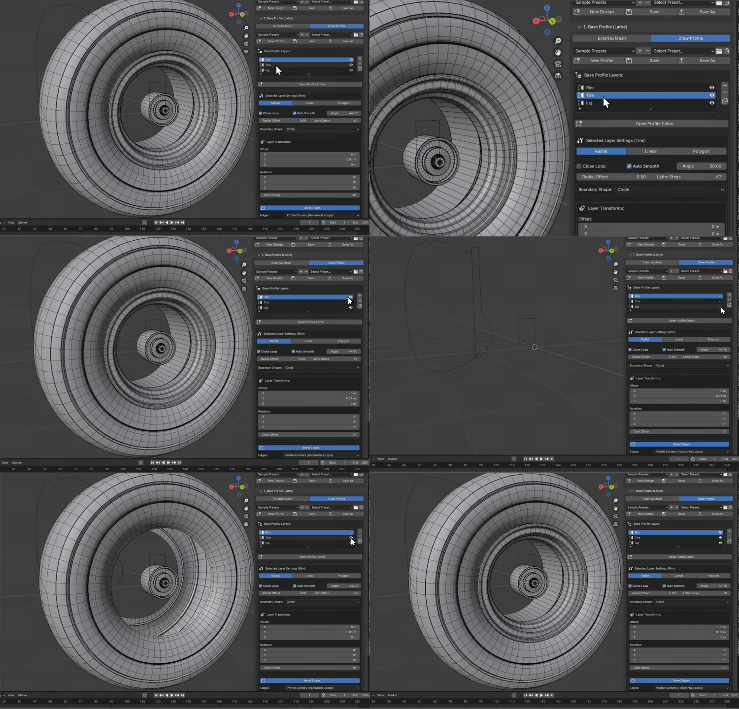
Profile Mode Configuration
Choose how the core mesh outline is defined:
- INTERNAL Mode: Construct and modify profile paths inside the viewport utilizing the custom 2D Canvas Editor.
- EXTERNAL Mode: Link an existing mesh object in your Blender Outliner to act as the source profile geometry.
Base Profile Layers
Pro-Radial supports stacking multiple profile layers. Click the + button to add a layer (e.g. Center Hub, spokes rim, outer tread). Each layer operates independently with its own shape and modifiers:

Interactive 2D Profile Editor
Inside Internal Mode, click Open Profile Editor to bring up the 2D coordinate grid editor directly inside the 3D Viewport. Here are the core visual modes for drawing and editing vertices:
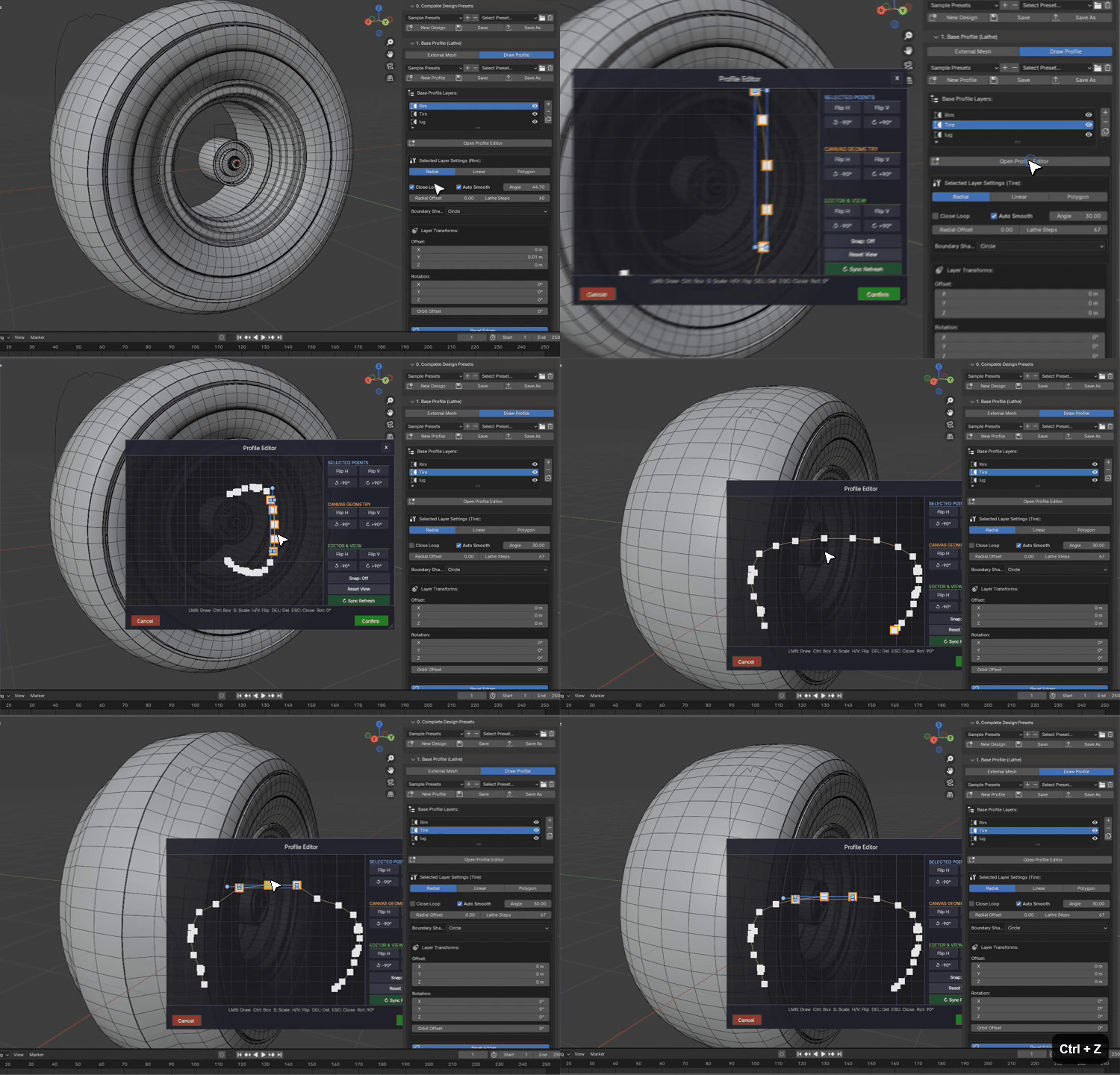
Clicking the Open Profile Editor button suspends regular Blender inputs and displays a high-tech 2D drafting canvas overlay. The canvas displays coordinate grid overlays and local center points, allowing you to draw profiles with millimetric precision.
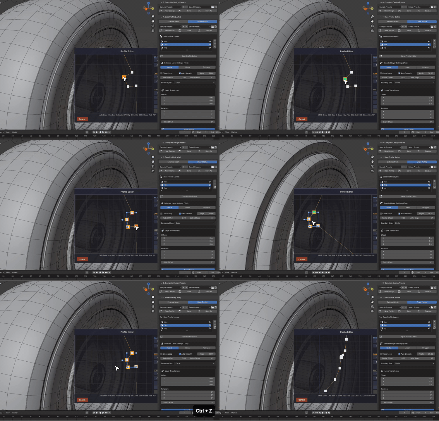
Adding Geometry: Left-click in the canvas grid coordinates to place new vertices. Vertices are connected sequentially to build a silhouette line. Press Ctrl+Z to undo, and Ctrl+Y to redo actions. Select points and press X or Delete to remove them.
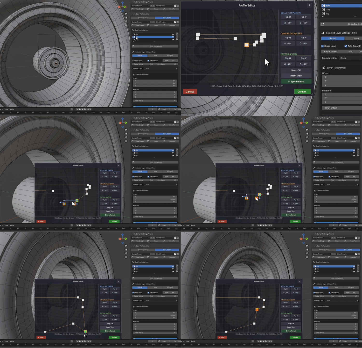
Layer Switching: Select a different layer in the Base Profile Layers list (such as Rim, Tire, or Lug) before opening the editor. This allows you to draw and manage independent curves for each part of the wheel assembly.

Selecting & Moving: Click and drag vertices to modify the profile shape. You can select multiple points and drag them together to adjust specific contours of your Rim profile with ease.
Layer Shape Types & Settings
Each layer can be set to one of the following generator types:
| Layer Shape Type | Description | Primary Properties |
|---|---|---|
| RADIAL | Sweeps the profile curve 360 degrees to generate standard lathe meshes (e.g. rims). | Close Loop, Lathe Steps, Radial Offset, Boundary Shape. |
| LINEAR | Extrudes a flat cross-section shape along a linear profile path (e.g., treads, segments). | Cross-Section Shape, Twist Angle, Corner Segments, Subdivisions. |
| POLYGON | Converts the profile points into a flat polygon and solidifies it along a flat depth vector. | Solidify Depth, Auto Smooth Angle. |
Boundary Shape Configurations
Under the Radial and Linear settings, you can constrain the sweep to geometric boundary shapes:

-
●
Standard Circles & Ellipses
Circle sweeps around a perfectly spherical constraint. Oval allows asymmetric horizontal/vertical scaling to create oval sweeps.
-
●
Rectangles & Capsules
Rectangle constrains the lathe to square dimensions. Specify width, height, and wall thickness. Capsule defines capsule boundaries with length and rounded radius caps.
-
●
Custom Boundary Curves
Selecting Custom opens a secondary Custom Shape Editor. This allows you to draw arbitrary non-circular outline paths that the lathe geometry will warp into.
Base Modifiers & Transform Parameters
| Parameter Name | Type | Default | Description |
|---|---|---|---|
| radial_offset | Float | 0.0m | Displaces the sweep radius outwards from the local center of coordinate rotation. |
| lathe_steps | Int | 32 | Resolution of the sweep. Higher numbers produce smoother curved geometry. |
| location_offset | Vector3 | (0,0,0) | Offsets the layer position in local 3D workspace coordinate space. |
| use_bevel | Boolean | False | Enables non-destructive bevel operations on the layer's output edges. |
| bevel_width | Float | 0.02m | Controls the thickness of the procedural edge bevel cuts. |
| mirror_mode | Enum | NONE | Allows mirroring the layer mesh output across X, Y, Z, or combined planes. |
2. Radial Elements (Arrays)
The Radial Elements panel manages arrays of objects—like spokes, bolt groups, fans, and treads—repeated in circular structures around the wheel hub.
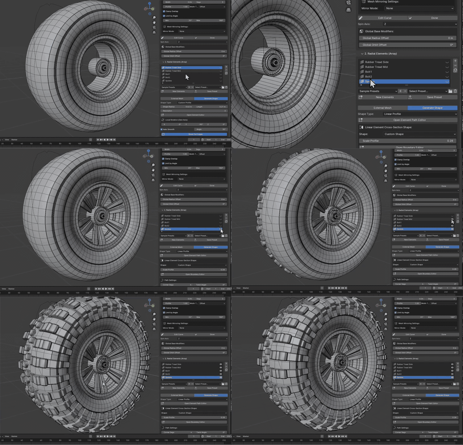
Elements Workflow
Generate spoke arrays procedurally or reference external source assets:
- Procedural Shapes: Choose from Circle, Rectangle, Capsule, Custom, or Linear sweep shapes. Open the custom element editor to draw profiles from scratch.
- External Objects: Pick any pre-existing mesh inside your Blender project using the viewport dropper. The array duplicates and warps the target mesh.
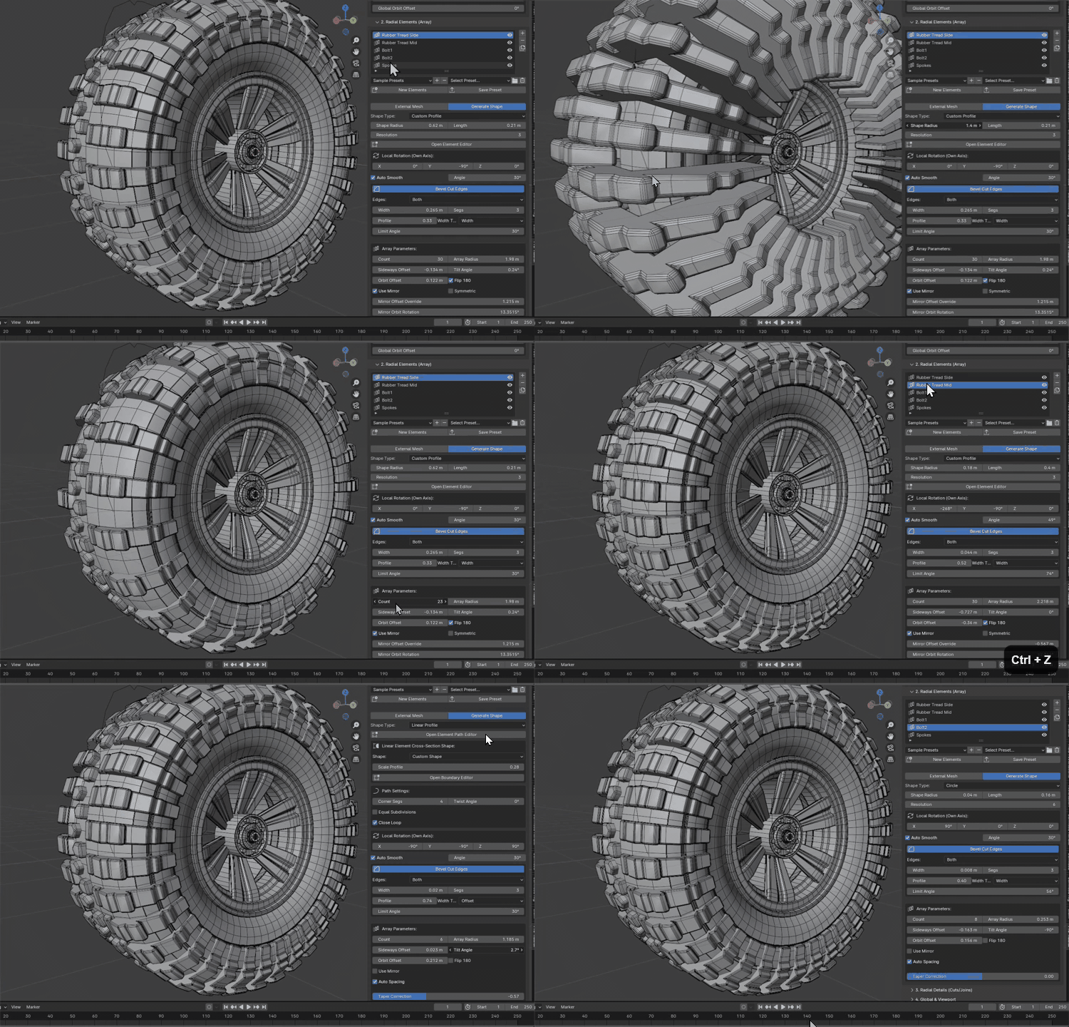
Spoke Array Parameters
Adjust these parameters under the Array Parameters sub-panel to modify array distributions:
| Parameter Name | Type | Default | Description |
|---|---|---|---|
| count | Int | 8 | The number of repeating elements in the circular array structure. |
| radius | Float | 1.0m | Array radius. Controls how far arrayed elements are shifted outward. |
| sideways_offset | Float | 0.0m | Shifts elements laterally, perpendicular to the radial offset lines. |
| tilt_angle | Float | 0.0° | Rotates each array element relative to its radial alignment axis (e.g. angled spokes). |
| auto_spacing | Boolean | True | Automatically distributes elements evenly around 360 degrees. |
| manual_gap | Float | 0.1 | Specifies the spacing gap when auto_spacing is disabled. |
| taper_correction | Float | 0.0 | Scales the thickness of elements as they extend toward the center to avoid mesh overlap. |
3. Radial Details (Cuts / Joins)
The Radial Details system runs real-time Boolean operations over the base lathe mesh. This is perfect for cutting out complex patterns, bolt holes, air vents, or joining panels without destructive modifications.
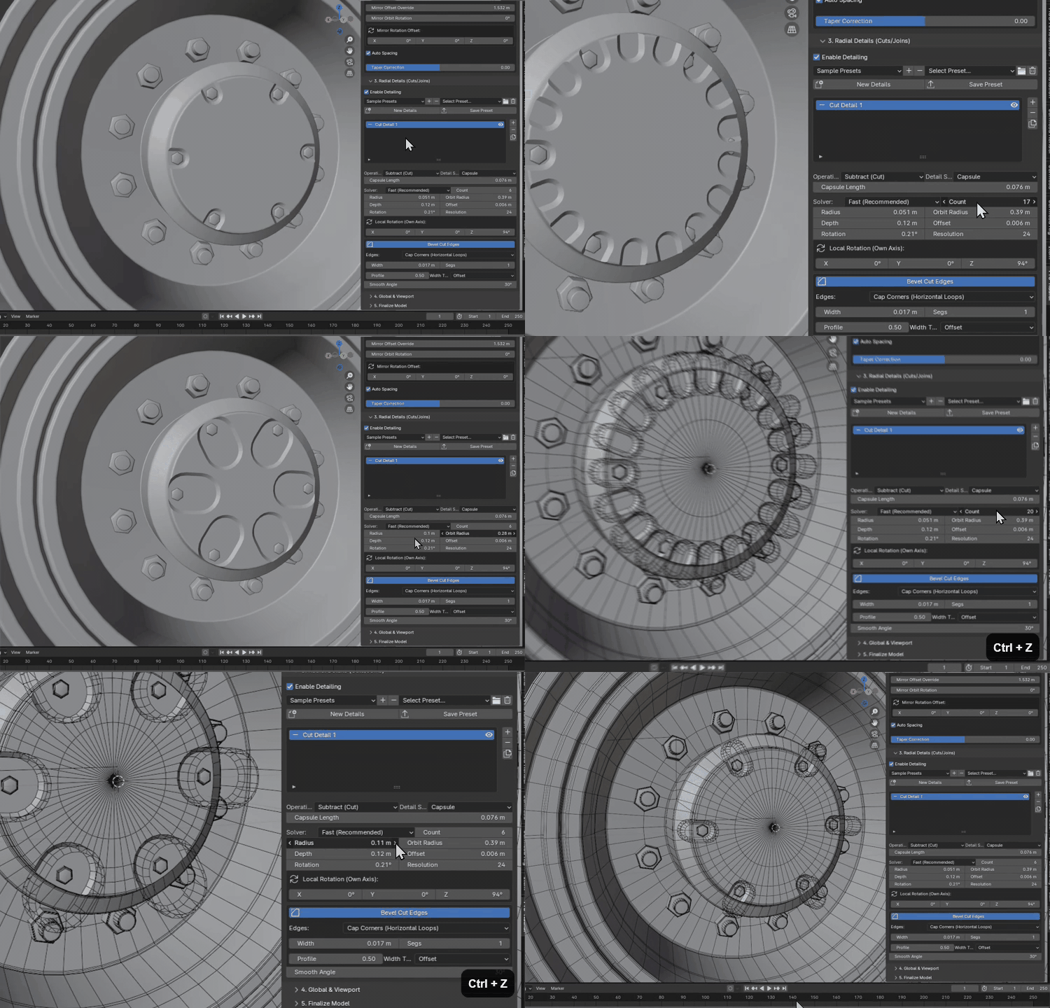
Boolean Detailing Workflow
How to configure detailing cuts on your radial meshes:
-
01
Enable Detailing Checkbox
Toggle Enable Detailing to activate the boolean engine. You can temporarily turn this off to optimize viewport performance.
-
02
Add Detail Operation
Click the
+button to create a new detail layer. You can set the operation mode to DIFFERENCE (cuts out holes) or UNION (fuses detailed shapes onto the mesh). -
03
Define Detail Shape
Select from Circle, Rectangle, Capsule, or Custom shapes. For custom cuts, click Open Detail Editor to draw the cutout profile in the 2D Canvas.
-
04
Configure Array Counts & Solvers
Set the number of repetitions using the Count slider. Set the solver to Fast for quick feedback, or Exact to handle overlapping geometries accurately.
Detail Parameters
| Parameter Name | Type | Default | Description |
|---|---|---|---|
| holes_op | Enum | DIFFERENCE | Boolean operations. DIFFERENCE cuts holes; UNION joins geometries together. |
| holes_count | Int | 5 | Determines how many times the detail is arrayed in a circle. |
| holes_orbit_radius | Float | 0.8m | The circular path distance from the center hub where the cuts occur. |
| holes_radius | Float | 0.05m | Controls the size/scale of the cut shape. |
| holes_offset | Float | 0.0m | Shifts the cut depth along the depth/rotational axis of the wheel. |
| use_bevel | Boolean | False | Enables non-destructive beveling on the inner cut edges to catch highlights. |
Exact boolean solver handles complex overlapping shapes perfectly, it requires significantly more computing power. For quick iterations, keep the solver on Fast.
4. Global & Viewport Settings
The Global Viewport panel controls the spatial alignment of the entire generator setup. Here, you define rotation axes, visibility, and global offsets.
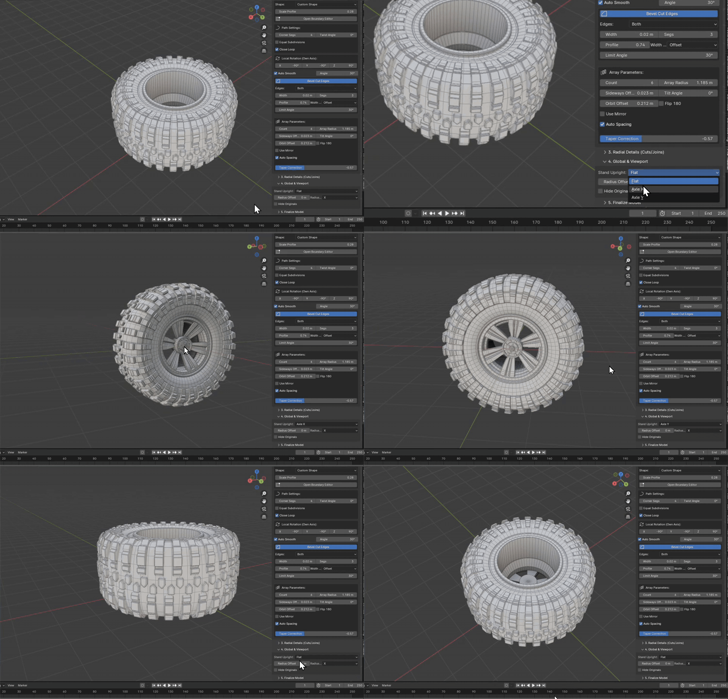
Viewport Configurations
Manage how generation helpers and workspace layouts behave:
Global Orientation Axis
Sets the main rotational axis for the lathe generator. Choose from X, Y, or Z. Toggle Stand Upright to align the model vertically in the viewport.
Base Radius Offsets
Applies a global offset multiplier to all profile layers and array radiuses. Ideal for scaling the entire wheel assembly while keeping component relationships intact.
Hide Source Objects
Automatically hides helper profile curves and external reference objects from the outliner. This keeps your viewport organized and prevents unwanted background rendering.
Base Spin Axis
Determines the coordinate system alignment vector for the lathe engine, controlling how vertices orbit around coordinates.
5. Mesh Finalization
Once you are satisfied with the procedural layout, you can collapse the node hierarchy into a standard, optimized static mesh.
-
01
Select Pro-Radial Procedural Object
Select the active procedural object group inside the viewport. Ensure all details are visible.
-
02
Execute "Create Final Mesh"
Scroll down to the 5. Finalize Model sub-panel and click the Create Final Mesh button.
-
03
Static Asset Created
Pro-Radial will duplicate the setup, apply all array and boolean modifiers, and generate a single clean, static mesh object named
PR_Final_Mesh, ready for uv-unwrapping, material mapping, or game engine exports.